The common and predominant way for applications requiring continuously modulated control - like keeping the shiplet in stable submerged balance - is to use a so called proportional–integral–derivative (PID) controller to calculate the actuators' actions based on the input of the sensor data in a continuous loop. As described in the former post Cybernetic Marine Mechatronics we use an MPU-6050 motion tracking devices to measure acceleration and rotation from its 3-axis gyroscope and 3-axis-accelerometer as input to control the positioning of the flaps and the fill-up or blow-off of air generating the buoyancy or downforce of the four side-gated tubular ballast tanks.
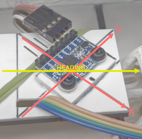
Since we are trying to keep things simple (but not sure that this will really work) the MPU-6050 is mounted diagonally with a 45 degree offset to the shiplets actual x and y axis so that its values for X and Y can be thought of as the idealized vertex positions, where each "corner" of the shiplet equals either X, Y, -X or -Y. We do not use the Z axis. The first corner [0] is heading portside nose, corner [1] is starboard nose, corner [2] is portside stern and corner [3] is starboard stern - resulting in:
acceleration[0] = (+Ay);
acceleration[1] = (+Ax);
acceleration[2] = (-Ax);
acceleration[3] = (-Ay);

rotation[0] = (+Gx);
rotation[1] = (-Gy);
rotation[2] = (+Gy);
rotation[3] = (-Gx);
In addition to the permanent equation of changing forces tilting the shiplet in various directions we also need to control the flotation depth of the submerged hull to keep the waterline in the desired position - usually in the middle between deck and hull - while driving. We can set the targeted depth via a turning knob at the remote control. Based on the variance between targeted and actual depth we calculate a slope which we add or subtract to the Ax and Ay position of each vertex so that the shiplet will either ascend or descend.
Regarding the attack angle of the flaps we assume that their efficacy will depend on the cruising speed of the shiplet - so we also want to take the shiplet's velocity into account. Finally we end up with this formula to calculate the servo position for each corner [lc], where the acceleration is the proportional and the rotation is the derivative:
servo_pos[lc] = (
    ((ACCELERATION_FACTOR * acceleration[lc]) +
    (ROTATION_FACTOR * rotation[lc])) *
    (DRIVING_SPEED_FACTOR / (DRIVING_SPEED_FACTOR +
    (driving_speed * driving_speed)))
);
The integral part of our PID controller is handled by the ballast tanks. To do so, we continuously calculate the average of the shiplets acceleration for each corner [lc] and trigger the pumps if the error exceeds a threshold and until the position changes to the better (indicating we are moving into the right direction):
if (height_recent > target_height)  // too high
{
    if ((acc_average[lc] > HEIGHT_TOLERANCE) and
        (acceleration[lc] >= acc_average[lc]))
    {
	deflate(lc);
    }
    else stop(lc);
}
if (height_recent < target_height)  // too low
{
    if ((acc_average[lc] < ((-1) * HEIGHT_TOLERANCE)) and
        (acceleration[lc] <= acc_average[lc]))
    {
	inflate(lc);
    }
    else stop(lc);
}
if (height_recent == target_height) stop(lc);
After the winter break we want to apply these formulas to the shiplet with a first guess for the contants. Et voilà - the result is quite impressive: at the right speed the shiplet passes a smooth test drive with sails:
![]()
One thought on “Promising PID Controller Calculation”
Comments are closed.